Zyxel XGS1210 series
The Zyxel XGS1210 series is a line of managed multi-gigabit Ethernet switches.
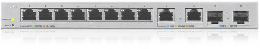
| Switch name | gigabit RJ45 ports | multi-gigabit RJ45 | SFP+ ports |
|---|---|---|---|
| XGS1010-12 | 8 | 2 (2.5G/1000M/100M) | 2 |
| XGS1210-12 | 8 | 2 (2.5G/1000M/100M) | 2 |
Architecture Overview
The XGS1210 platform makes use of the various SerDeS units on the RTL9302.
| SDS | Use |
|---|---|
| 2 | RTL8218D |
| 6 | RTL8226 |
| 7 | RTL8226 |
| 8 | SFP+ |
| 9 | SFP+ |
Models
Hardware
- RTL9302B SoC
- Macronix MX25L12833F (16MB flash)
- Nanja NT5CC64M16GP-1 (128MB DDR3 SDRAM)
- RTL8231 GPIO extender to control the port LEDs
- RTL8218D 8x Gigabit PHY
- 2 RTL8226 2.5 Gigabit PHYs
2 Uplink ports are SFP+ cages which support 10GBit Base-X mini GBIC modules.
Power is supplied via a 12V 1.5A standard barrel connector. At the right side behind the grid is UART serial connector. A Serial header can be connected to from the outside of the switch trough the airvents with a standard 2.54mm header. Serial connection is via 115200 baud, 8N1.
Pinout of J5 is from top to bottom:
  1 Vcc(3.3V) --\
  2 TX --------\ |
  3 RX ------\ | |
  4 GND ---\ | | |
           | | | |
Power consumption
Initial power measurements using a single port, under no load. Measurements are being done by a DGS-1100-8P PoE+ switch

OEM U-Boot shell (without rtk network on) the consumption is 6.0Watts
OEM XGS-1010-12 firmware 7.5Watts
OpenWRT snapshot 7.6Watts
Port & LED numbers
The RTL9302 SoC supports 24 GbE ports, and four 10G ports.
Device ports 1-8 are switch ports 0-7. Device ports 9-12 are switch port 24-27. Ethernet port 1 (eth0) is switch port 28.
| Ports | LED index | LED comment |
|---|---|---|
| 1-8 | 0 | Amber component of Bi-color Amber/Lime-Green LED. LED0 must be off. |
| 1-8 | 1 | Lime-Green component of Bi-color Amber/Lime-Green LED. LED1 must be off. |
| Ports | LED index | LED comment |
| 9-10 | 0 | Multi-LED selection. 0 chooses the Amber/Lime-Green Bi-color LEDs. 1 chooses the RGB LEDs. |
| 9-10 | 1 | LED0 = 0: amber, LED0 = 1: red |
| 9-10 | 2 | LED0 = 0: green, LED0 = 1: green |
| 9-10 | 3 | LED0 = 0: (none), LED0 = 1: blue |
| Ports | LED index | LED comment |
| 11-12 | 0 | Blue |
| 11-12 | 1 | Lime-Green |
Board details


Close up of the strapping pins match what we get from peripherial address 0xb8000100: 0x0080200 0b1000000001000000000. It doesn't tell us what is what however, when looking at https://gitlab.com/olliver/openwrt/realtek_sdk/-/blob/openwrt-dev/loader/u-boot-2011.12/arch/otto40/plr/src/platform/9300/register_map.h#L346 or the datasheet:

XGS1010-12
The XGS1010-12 is identical to the XGS1210-12 in hardware, only the software is different or rather, lack of. The XGS1010-12 contains only the minimal amount of software, to setup and initialize the chips, to actual perform its switching job. While it self-assigns an IP (192.168.1.1), this IP cannot ping or be pinged from Linux. In U-Boot however it can be used after executing rtk network on, to do tftp transfers.
Because the switch is not reachable during normal operation, performing a firmware update is also not possible through this way. The serial port however is available and usable, and can be used to initiate tftpboot or upload software through XYZ-modem variants.
The upside is that due to the very little software on this switch, no configuration data sits there to be corrupted.
NOTE: Buyer beware. While the XGS1010-12 is the identical in hardware _today_, this may not always be the case and cost reductions may lead to smaller flash and smaller RAM chips. While the flash chip is easily replaced, the RAM chip is not. Also, because the switch is not intended to be managed, there is no MAC address provisioned for the switch, bar the SDK hardcoded environment variable Realtek OU part of the MAC address.
OEM Firmware
OEM U-Boot environment
RTL9300# # printenv
baudrate=115200
boardmodel=RTL8393M_DEMO
bootcmd=boota
bootdelay=1
ethaddr=00:E0:4C:00:00:00
ipaddr=192.168.1.1
ledModeInitSkip=0
serverip=192.168.1.111
stderr=serial
stdin=serial
stdout=serial

Environment size: 217/65532 bytes
OEM bootlog
OEM tech-support
By tftpbooting the XGS1210-12 `.bix` file, we get into the Zylinx shell, which while restrictive, allows us to do `show tech-support`.
Board GPIO
Device  Pin  Direction  Default  Current  Purpose
------- ---- ---------- -------- -------- --------
INT      0   OUT        0        0        SYSTEM-LED
INT      1   N/A                          Not Connected
INT      2   N/A                          Not Connected
SPI      3   N/A                          Goes to unpopluated U23 (SPI_CLK)
SPI      4   N/A                          Goes to unpopluated U23 (SPI_MISO)
SPI      5   N/A                          Goes to unpopluated U23 (SPI_MOSI)
INT      6   IN         0        0        Permanently Pulled down, likely to indicate presence of U23
INT      7   IN         1        1        Permanently Pulled up, likely to indicate presence of ...?
I2C	 8   OUT                          Shared SFP clock (SFP0/SFP1: SCK) Pull-up near SFP0
I2C	 9   I/O                          SDA0: (SFP0_SDA) Pull-up near SFP0
I2C	10   I/O                          SDA1: (SFP1_SDA) Pull-up near SFP1
INT     11   OUT        0        0        Transmit Disable (SFP0: TX_DIS_FX) Pull-up near SFP0
INT     12   IN         0        0        Absent detection (SFP0: MOD-DEF0) Pull-up near SFP0
INT     13   IN         0        0        Los of Signal (SFP0: LOS) Pull-up near SFP0 (pull down NP option)
INT     14   IN         0        0        Transmit Fault (SFP0: TX_FAULT) Pull-up near SFP0
INT     15   OUT        0        0        Transmit Disable (SFP1: TX_DIS_FX) Pull-up near SFP1
INT     16   IN         0        0        Absent detection (SFP1: MOD-DEF0) Pull-up near SFP1
INT     17   IN         0        0        Los of Signal (SFP1: LOS) Pull-up near SFP1 (pull down NP option)
INT     18   IN         0        0        Permanently pulled down? Trace not found ...
INT     19   IN         0        0        Permanently pulled down? Trace not found ...
INT     20   OUT        0        0        Goes to U10?
INT     21   IN         0        0        Transmit Fault (SFP1: TX_FAULT) Pull-up near SFP1
INT     22   OUT        1        1        Reset_PHY?
INT     23   IN                           Reset Button
Note, that RS0/RS1 for both SFP's have permanent pull-ups, but also have the pull-down option. Not connected/lost traces can still exist on an internal layer (Reset for example).
USB
While this switch has no USB ports, the USB pins appear to be on TP2 and TP3 on the bottom (to be confirmed)
The OEM OS boots into the Realtek SDK diag application, which can be exited with exit to get dropped into a Busybox shell. Because the switch is not managed, no network initialization happens, making for a pretty fast boot.
OEM Flash layout
U-Boot
RTL9300# # flshow
=============== FLASH Partition Layout ===============
Index  Name       Size       Address
------------------------------------------------------
 0     LOADER     0xe0000    0xb4000000-0xb40dffff
 1     BDINFO     0x10000    0xb40e0000-0xb40effff
 2     SYSINFO    0x10000    0xb40f0000-0xb40fffff
 3     JFFS2_CFG  0x100000   0xb4100000-0xb41fffff
 4     JFFS2_LOG  0x100000   0xb4200000-0xb42fffff
 5     RUNTIME1   0x680000   0xb4300000-0xb497ffff
 6     RUNTIME2   0x680000   0xb4980000-0xb4ffffff
======================================================
Linux
# cat /proc/mtd
dev:    size   erasesize  name
mtd0: 000e0000 00001000 "LOADER"
mtd1: 00010000 00001000 "BDINFO"
mtd2: 00010000 00001000 "SYSINFO"
mtd3: 00100000 00001000 "JFFS2 CFG"
mtd4: 00100000 00001000 "JFFS2 LOG"
mtd5: 00680000 00001000 "RUNTIME"
mtd6: 00680000 00001000 "RUNTIME2"
OEM U-Boot Self-test failure
============= Factory Test Begin =============
HTP log info get: htpModeIf=1, htpBreakIf=0, hour=20, entry=12800, round=808859448 !
HTP Test log full!
============= Factory Test End ! =============
The OEM bootloader (U-Boot 2011.12.(TRUNK_CURRENT)-svn99721 (Oct 24 2019 - 09:15:40)) runs a self-check upon startup. This check byte is in the middle of the flash, stored at address `0x810000` (just beyond the 8MiB marker) on the XGS1010-12. With the recently new introduced mtd-concat, we can however define two regions and concatate those logically in Linux. The upside is, unless Zyxel recompiled their firmware (unnecessary work for them, but possible), using a smaller flash-chip would be less-likely.
As an alternative, the XGS1210-12 U-Boot binary can be flashed, which turns the XGS1010-12 'more' into a XGS1210-12, which puts this self-check at the end of the flash.
References
XGS1210-12
OEM Firmware
It ships with a u-boot bootloader (U-Boot Version V1.0.0.1 (Oct 14 2019 - 17:51:23)) based on Realtek's SDK for RTL93xx SoCs and Linux 3.18 based on Realtek's SDK 3.x. It has a web interface for all management functions.
OpenWRT Bootlog
OpenWrt Support
There is experimental OpenWrt support: the device boots and the Ethernet and switch driver function. The 1 and 2.5 GBit ports work, but not the SFP+ cages. No GPIO support so far.